Bidirectional Magnetic Field Press
The PLC of DXP25-300 Bidirectional Magnetic Field Press uses the OMRON company controller, and all actions are centrally controlled by the PLC.
When the electromagnetic coil passes current, a spatial magnetic field with relatively parallel magnetic lines of force is generated between the two pole heads, thereby achieving the purpose of orienting the magnetic powder.
The oil cylinder is controlled by the hydraulic system to implement actions such as suppression and return.
1. Working Conditions
- 1.1 Power supply: Gross power 30KW, Three-phase, 50Hz.
- 1.2 Cooling water: About 0.2 MPa.
- 1.3 Hydraulic oil: 32# hydraulic oil.
2. Main Technical Index
2.1 Hydraulic System
- 2.1.1 System pressure: 16 MPa.
- 2.1.2 Stroke of upper cylinder: 200 mm.
- 2.1.3 Stroke of lower cylinder: 200 mm.
- 2.1.4 Oil cylinder speed:
- Fast-forward: 50 mm
- Counter pressure: 20–40 mm
- 2.1.5 The oil pump selects the ATOS vane pump (Elmfluid).
- 2.1.6 Motor power: 7.5 KW.
2.2 Electromagnet
- 2.2.1 Pole diameter: 300 mm.
- 2.2.2 Pole head diameter: 150 mm.
- 2.2.3 Magnetic field (100 mm air gap): ≥1.4 T.
- 2.2.4 The electromagnet's long-term continuous working temperature rise is ≤40°C.
2.3 Work Beat
Work Beat:<10s.
3. Installation Conditions
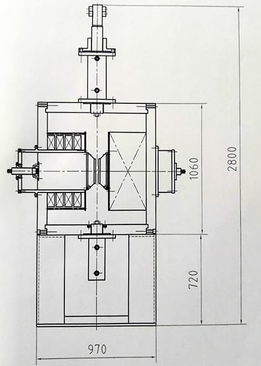
The anchor hole is 4 - Φ26, which can not be fixed, but needs to be leveled basically.
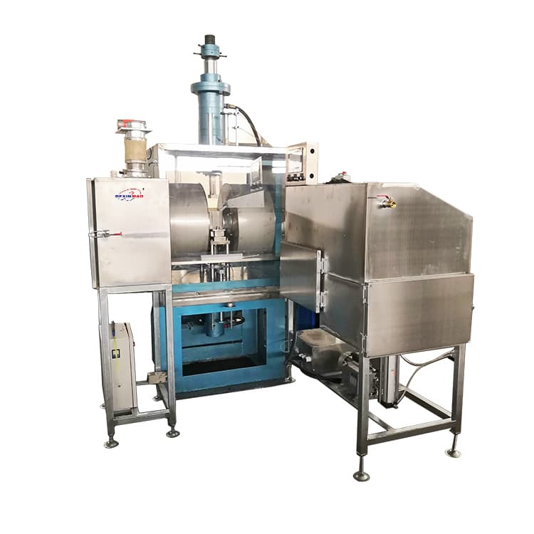
The general layout is as follows: the hydraulic station is at the right rear of the main engine, and the electric control cabinet is in front of the right side of the main engine.
The power incoming line requires three-phase + zero line + ground wire. The air switch and wire diameter are selected according to the total power.
Recommended value:
- 100A air switch
- 10mm² phase line
The hydraulic system needs about 170kg of 32# or 46# hydraulic oil, which is added through the filter above the oil tank cover.
There are coolers in the electromagnet and hydraulic station of the machine, which can work continuously only by connecting the cooling circulating water.
There are 3 pairs of inlet and outlet nozzles of the cooler, and all the outer diameters are Φ26.
4. Structural Principle
This machine is composed of three parts:
- Main engine
- Electronic control
- Hydraulic pressure
4.1 Main Engine Part
It is mainly composed of base, electromagnet and oil cylinder.
The electromagnet is the core of the magnetic field. When the electromagnetic coil passes through the current, the magnetic circuit formed by the yoke and pole produces a space magnetic field with the magnetic lines of force relatively parallel between the two poles, so as to achieve the purpose of magnetic particle orientation.
The cylinder is controlled by the hydraulic system to realize the action of pressing and returning.
4.2 Electronic Control Part
It is mainly composed of the cabinet, operation panel, PLC and related components, DC power supply and related components, sensors, etc.
The PLC of this machine adopts the OMRON company controller, and all actions are controlled by the PLC.
The direct current power supply provides the electromagnet with continuously adjustable forward and reverse direct current.
The sensor of this machine has a proximity switch to limit the position of the oil cylinder.
4.3 Hydraulic Pressure Part
It mainly comprises an oil tank, oil pump, manifold block and hydraulic valve.
The oil pump is a two-stage vane pump with a rated pressure of 21MPa.
The hydraulic valve has an electromagnetic directional valve, electromagnetic relief valve, etc.
The solenoid valve is controlled by the electric control system to change the direction of the pressure oil flow and realize the control of the oil cylinder.
5. Operation Method
5.1 Action Program
This machine has two working modes:
- Manual
- Automatic
Both are controlled by PLC.
In manual mode, each action is generally used for adjustment and maintenance, while automatic mode is used for normal continuous operation.
The operation procedure of automatic mode is as follows:
The automatic mold is placed between the two poles with adjusted spacing and clamped.
Press the "cycle" button → stop the lower cylinder (loading) → press the "cycle" button again → the upper cylinder and the lower cylinder close the mold and stop → the DC orientation → the orientation value reaches the maximum setting → the upper and lower cylinders simultaneously press → maintain pressure → demagnetize → upper cylinder upper → lower cylinder upper ejection stop → reclaim.
Then go back to execution.
5.2 Operating Procedures
5.2.1 Startup Steps
- Verify that the machine is trouble free.
- Press the "power switch" button on the operation panel of the electric control cabinet.
- Press the "pump line" button and confirm that the oil pump motor is started.
- Enter normal operation.
5.2.2 At Work
- Confirm that the "manual / automatic" transfer switch is set to the corresponding "automatic".
- The operator puts the mold in the working position correctly and then leaves the hand.
- Click the "cycle" button.
- The press operates according to the preset program.
5.2.3 Shutdown Procedure
- Press the "pump stop" button to turn off the oil pump motor.
- Press the "power" button to turn off the panel power.
5.3 Adjustment Method
5.3.1 Pressure Adjustment
- Turn on the machine step by step.
- Set the "manual / automatic" transfer switch to "manual".
- Put the mold or substitute in the working position correctly and then leave the hand.
- Press and hold the "upper cylinder ↓" button until the mold or substitute is pressed.
- The pressure gauge shows the current pressure.
- Rotate the hand wheel of the solenoid relief valve at the bottom right of the pressure gauge to change the pressure.
- Read from the pressure gauge in the direction of large and reverse small.
5.3.2 Orientation Adjustment of Demagnetization Current
- Turn on the machine step by step.
- Set the "manual / automatic" transfer switch to "manual".
- Clamping die or non-magnetic block between two poles.
- Turn the potentiometer counter clockwise to zero.
- Press the "orientation" button and rotate the orientation potentiometer clockwise to gradually increase the orientation current from zero.
- The demagnetization current adjustment method is the same as above.
Special Attention
The orientation adjustment potentiometer is in the operation panel, and the demagnetization adjustment potentiometer is outside.
Standard value of orientation current: 75A.
Maximum demagnetizing current: 20A, which can be adjusted as required.
5.3.3 Limit Switch Adjustment
The proximity switch is used as the limit position of the oil cylinder.
The sensing head of the proximity switch should be adjusted to 1–3 mm away from the disc of the guide rod head in advance.
The proximity switch seat should be moved up and down according to the need, and locked with the jacking screw after it is in place.
5.3.4 Pole Spacing Adjustment
The pole head is adjusted by hand wheel, forward and backward.
5.3.5 Press Time Adjustment
The pressing time is programmed.
5.4 Matters Needing Attention
- 5.4.1 Observe the operation rules and ensure the safety of the person.
- 5.4.2 Each adjustment shall be carried out by a specially assigned person and shall not exceed the limit or miss the steps.
- 5.4.3 In case of equipment failure during operation:
- Press the "emergency stop" button.
- Observe and remove the fault or shut down the machine in normal order for repair.
- Special attention: Do not turn off the power directly.
- 5.4.4 The front and rear doors of the electric control cabinet should not be opened casually to prevent electric shock.
- 5.4.5 Before switching on and off, the current state must be verified. If the fault is not removed, the machine cannot be turned on, and the machine cannot be shut down until the action is over.
6. Maintenance and Repair
6.1 Routine Maintenance
- 6.1.1 Special personnel shall be designated to regularly check the electrical and hydraulic components and their connections and wiring, and timely replace or fasten them in case of damage and looseness.
- 6.1.2 Pay attention to the temperature of the electromagnet shell at ordinary times.
If the hand feeling is obviously higher than the normal value, check according to the following steps:
Power on → Set manual → Clamping die or non-magnetic block between poles → Press and hold the "orientation" button until the current rises to a stable value.
If it exceeds 75A, it should be adjusted to 75A according to the regulations.
If it is less than 75A, check whether the cooling water is unobstructed, including the total water in and out and the water in and out of each group of water discharge, so as to ensure complete patency.
- 6.1.3 Clean the oil pump filter once a year (take it out from the filter hole above the tank cover).
- 6.1.4 The hydraulic oil is filtered or replaced every two years.
- 6.1.5 If the cooling circulating water is not softened, the acid washing water should be discharged once a year.
6.2 Troubleshooting
6.2.1 Unable to Power On
- Check the power supply (main power supply, cabinet power supply, panel power supply) and air switches.
- Check the "pump running", "pump stop" buttons and oil pump motor contactor.
- If the input and output voltage in the cabinet is normal, check the motor and wiring finally.
6.2.2 No Action After Startup
Check:
- Whether the "emergency stop" button is pressed (unlocking is normal).
- Whether the photoelectric switch is offset or blocked (0104 light on PLC is off as normal).
- Check the status of "run / set" and "manual / automatic" change-over switch.
- Check whether the wiring of each button and switch is loose.
- Check all fuses and wiring.
- Check PLC status (POW and RUN lights are normal) and wiring.
- Check the wiring of each terminal.
6.2.3 Stop the Action
Check:
- Power supply.
- Whether the photoelectric switch is mistakenly shifted or the "emergency stop" button is touched by mistake.
- Whether the orientation current is lower than 60A (standard value 75A).
- All fuses and wiring.
- PLC status (POW and RUN lights are normal) and wiring.
- Wiring of each terminal.
6.2.4 Orientation and Demagnetization Current Decrease or Disappear
First, judge whether there is a problem with orientation or demagnetization.
If one of them is normal, check the adjusting potentiometer and contactor of the other circuit.
If both are abnormal, check:
- Observe whether there is the red light on the trigger board. If there is, it means phase loss.
- Check all fuses and wiring.
- Check the three thyristor modules.
- Check power transformer, synchronous transformer and wiring.
- Check potentiometer, contactor and wiring.
- Check and arrange rectification circuit.
- Generally, the insulation degree of the swing coil should be more than 200MΩ.
6.2.5 Hydraulic System Pressure is Unstable, Reduced or Disappeared
Check:
- Oil quality, oil level and oil filter at the pump suction.
- Oil inlet and outlet of oil pump for air leakage and oil leakage.
- Clean the relief valve.
- Solenoid valve and its related lines.
- Whether the oil pump, motor and coupling are damaged.
- Seal of the oil cylinder piston and guide sleeve.
7. PLC Program
The PLC of this machine adopts OMRON PLC and ladder diagram programming.
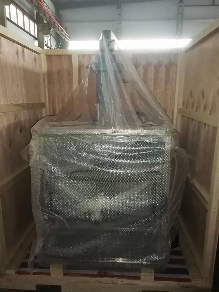
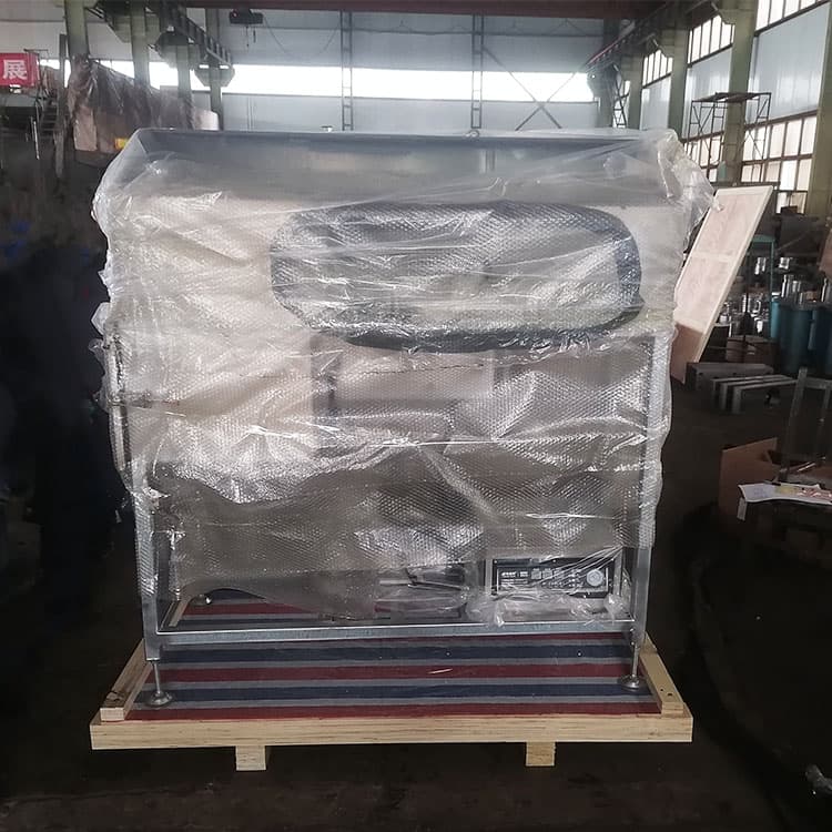
Packaging